National Oilheat Research Alliance 61
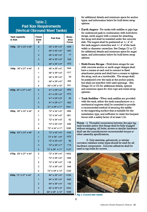
Table 2.
Pad Size Requirements
(Vertical Obround Steel Tanks)
Tank capacity
& Size
Flood
Zone
#
Pad Size Bouyancy
Force
120g 30" x 23" x 46" 0 48" x 35" x 6" -499
1 48" x 35" x 6" -293
2 48" x 35" x 6" 17
3 48" x 35" x 6" 326
4 48" x 35" x 9" 532
130g 30" x 27" x 44" 0 48" x 39" x 6" -544
1 48" x 39" x 6" -317
2 48" x 39" x 6" 38
3 48" x 39" x 6" 394
4 48" x 39" x 10" 631
220g 49" x 27" x 44" 0 61" x 39" x 6" -850
1 61" x 39" x 6" -472
2 61" x 39" x 6" 95
3 61" x 39" x 7" 662
4 61" x 39" x 11" 1041
230g 60" x 22" x 44" 0 72" x 34" x 6" -896
1 72" x 34" x 6" -501
2 72" x 34" x 6" 92
3 72" x 34" x 6" 685
4 72" x 34" x 11" 1080
240g 60" x 23" x 46" 0 72" x 35" x 6" -935
1 72" x 35" x 6" -523
2 72" x 35" x 6" 96
3 72" x 35" x 7" 715
4 72" x 35" x 11" 1127
275g 60" x 27" x 44" 0 72" x 39" x 6" -1042
1 72" x 39" x 6" -568
2 72" x 39" x 6" 138
3 72" x 39" x 8" 848
4 72" x 39" x 12" 1320
330g 72" x 27" x 44" 0 84" x 39" x 6" -1236
1 84" x 39" x 6" -669
2 84" x 39" x 6" 182
3 84" x 39" x 8" 1032
4 84" x 39" x 12" 1599
for additional details and minimum specs for anchor
types, and information below for hold-down strap
options.
• Earth Augers - For tanks with saddles or pipe legs
for undersized pads in combination with hold-down
straps, earth augers with a means for attaching
the strap end shall be installed under the concrete
slab. The augers shall be positioned at +/- 4" of
the tank support centerline and +/- 4" of the tank
width or diameter centerline. See Design C1 or C2
for additional details and minimum specs for auger
types, and information below for hold-down strap
options.
• Hold-Down Straps – Hold-down straps for use
with concrete anchor or earth auger designs shall
have a means at each end to connect to fixed
attachment points and shall have a means to tighten
the strap, such as a turnbuckle. The straps shall
be positioned over the tank at the anchor points,
but shall not interfere with used openings. (See
Design D1 or D2 for additional details, options
and minimum specs for wire rope and metal strap
options).
• Tank Saddles – When tank saddles are provided
with the tank, either the tank manufacturer or a
mechanical engineer shall be consulted to provide
a recommended method of securing the saddle
to the supporting surface that is suitable for the
installation type, and sufficient to resist the buoyant
forces with a safety factor of at least 1.15.
Notes – 1. Threaded connections between the pipe leg,
tank bracket and/or foot flange shall be fully engaged
without stripping. All bolts, screws or similar hardware
shall use the manufacturers recommended torque or
other assembly specifications.
2. Only stainless, galvanized, or similar
corrosion resistant metal types should be used for all
hardware components. Concrete adhesives shall be
used in tap holes for screws.
Fig. 2. Concrete slab remesh
3