60 National Oilheat Research Alliance
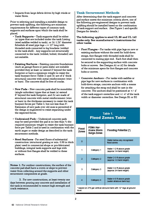
Table 1.
Flood Zones Table
Flood
Zones
FEMA Hurricane
Storm
Surge Zones
Flooding Potential (*)
0 Water below any recognized
flood zones
1 Category 1 Water 1-2 ft above grade
(approx 1/4 tank height)
2 Category 2 Water 2-3 ft above grade
(approx 1/2 tank height)
3 Category 3 Water 3-4 ft above grade
(approx 3/4 tank height)
4 Category 4 Water 4-5 ft above grade
(water at/above tank top)
* based on 275 gal vertical obround tank with 12" legs at ground
level.
• Impacts from large debris driven by high winds or
water flows.
Prior to selecting and installing a suitable design to
prevent tank uplifting, the following are minimum
requirements for different types of common tank
supports and surfaces upon which the tank shall be
placed.
• Tank Supports – Tank supports shall be either
(a) types that are included under the tank Listing
(steel saddles welded to tank), or (b) 1.25" diameter
Schedule 40 steel pipe legs <= 12" long with
threaded ends connected to leg brackets (welded
to the tank shell). Any supports not structurally
connected to the tank (welded, bolted, threaded) are
not suitable.
• Existing Surfaces – Existing concrete foundations
(such as garage floors or patio slabs) are suitable
provided they at least (a) extend 3' beyond the tank
footprint or have a minimum weight to resist the
tank buoyant force (Table 2) and (b) are of 4" thick
structural concrete with metal reinforcement (wire
or bars). The concrete shall be free of cracks.
• New Pads – New concrete pads shall be monolithic
(single unbroken) types that at least (a) extend
6" beyond the tank footprint, and (b) are made of
structural concrete with metal reinforcement (wire
or bars) in the thickness necessary to resist the tank
buoyant forces per Table 2, but not less than 6".
Extension of new pads over old ones is permitted if
the design is engineered to resist separating under
the expected forces.
• Undersized Pads – Undersized concrete pads
may be used provided the pad is no less than ½ the
required minimum weight to resist the tank buoyant
force per Table 2 and is used in combination with the
earth auger or stake design as described in the tank
securement methods.
• Steel Surfaces - For steel floors of substantial
construction (structural grating or min. 0.93 in thick
plate) used in commercial shops or pre-fabricated
buildings, integral tank supports and legs with
or without foot flanges shall be welded to these
surfaces.
Notes- 1. For outdoor constructions, the surface of the
concrete pad shall have a crown or slope to prevent
water from collecting around the supports and other
securement components at grade.
2. For new constructions, at least twenty one
days between pouring any concrete and installation of
the tank is recommended to ensure high strength and
crack resistance.
Tank Securement Methods
After determining that the tank support and concrete
pad surface meets the minimum criteria above, one of
the following pre-engineered designs to prevent tank
uplifting should be installed based on the combination
of tank support and surface. (See Figure 1 and specific
Designs for details.)
The following applies to steel UL 80 and UL 142
tanks only. See manufacturer’s instructions for
other tanks.
• Foot Flanges – For tanks with pipe legs on new or
existing surfaces without the need for hold-down
straps, foot flanges with threaded ends shall be
connected to mating pipe end. Each foot shall then
be secured to the supporting surface with concrete
bolts or screws. See Designs A1 or A2 for details
of the minimum specs for foot flanges and concrete
bolts or screws.
• Concrete Anchors – For tanks with saddles or
pipe legs for new surfaces in combination with
hold-down straps, concrete anchors with a means
for attaching the strap end shall be cast in the
concrete. The anchors shall be positioned at +/- 4"
of the tank support centerline and +/- 4" of the tank
width or diameter centerline. See Design B1 or B2
2