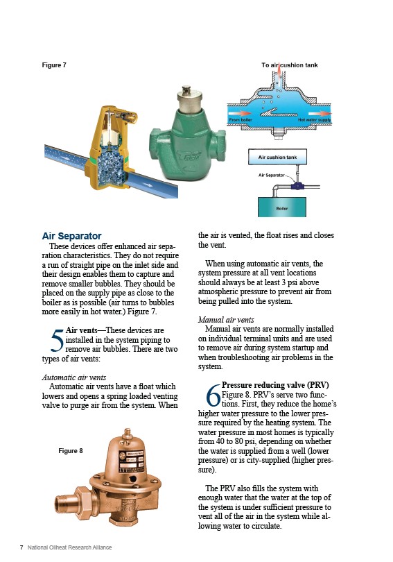
Figure 7
Air Separator
These devices offer enhanced air separation
characteristics. They do not require
a run of straight pipe on the inlet side and
their design enables them to capture and
remove smaller bubbles. They should be
placed on the supply pipe as close to the
boiler as is possible (air turns to bubbles
more easily in hot water.) Figure 7.
5 Air vents—These devices are
installed in the system piping to
remove air bubbles. There are two
types of air vents:
Automatic air vents
Automatic air vents have a float which
lowers and opens a spring loaded venting
valve to purge air from the system. When
Figure 8
7 National Oilheat Research Alliance
the air is vented, the float rises and closes
the vent.
When using automatic air vents, the
system pressure at all vent locations
should always be at least 3 psi above
atmospheric pressure to prevent air from
being pulled into the system.
Manual air vents
Manual air vents are normally installed
on individual terminal units and are used
to remove air during system startup and
when troubleshooting air problems in the
system.
6Pressure reducing valve (PRV)
Figure 8. PRV’s serve two functions.
First, they reduce the home’s
higher water pressure to the lower pressure
required by the heating system. The
water pressure in most homes is typically
from 40 to 80 psi, depending on whether
the water is supplied from a well (lower
pressure) or is city-supplied (higher pressure).
The PRV also fills the system with
enough water that the water at the top of
the system is under sufficient pressure to
vent all of the air in the system while allowing
water to circulate.