Chapter 4
Best Boiler Piping Practices
Purge valve—this location enables the
technician to quickly remove air from the
entire system. By closing the isolation valve(s),
manually closing the zone valves one at a time
and then opening the purge valve, water can
be forced to flow through, and completely fill,
each zone.
Isolation valve—this valve enables quick
service of system components and isolates the
purge valve from the pressure reducing valve,
forcing water to flow through the system and
back to the purge valve. This should be a gate
or ball valve; globe valves should NOT be
used.
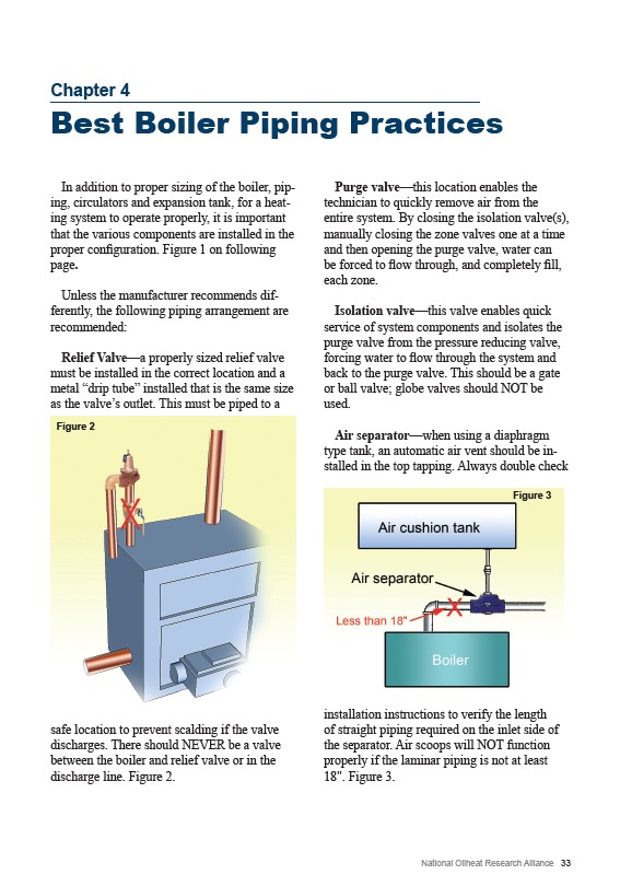
Air separator—when using a diaphragm
type tank, an automatic air vent should be installed
in the top tapping. Always double check
Figure 3
installation instructions to verify the length
of straight piping required on the inlet side of
the separator. Air scoops will NOT function
properly if the laminar piping is not at least
18". Figure 3.
National Oilheat Research Alliance 33
In addition to proper sizing of the boiler, piping,
circulators and expansion tank, for a heating
system to operate properly, it is important
that the various components are installed in the
proper configuration. Figure 1 on following
page.
Unless the manufacturer recommends differently,
the following piping arrangement are
recommended:
Relief Valve—a properly sized relief valve
must be installed in the correct location and a
metal “drip tube” installed that is the same size
as the valve’s outlet. This must be piped to a
Figure 2
safe location to prevent scalding if the valve
discharges. There should NEVER be a valve
between the boiler and relief valve or in the
discharge line. Figure 2.