Chapter 1
Hydronic System Components
5 National Oilheat Research Alliance
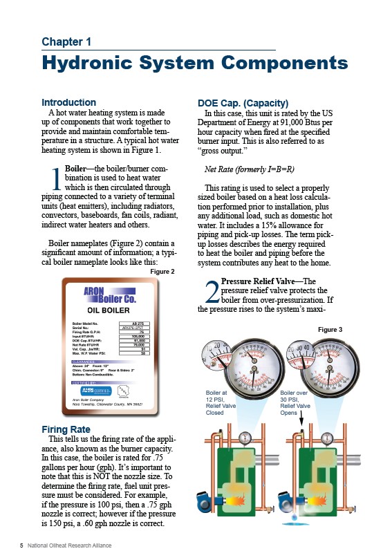
Figure 3
Introduction
A hot water heating system is made
up of components that work together to
provide and maintain comfortable temperature
in a structure. A typical hot water
heating system is shown in Figure 1.
1 Boiler—the boiler/burner combination
is used to heat water
which is then circulated through
piping connected to a variety of terminal
units (heat emitters), including radiators,
convectors, baseboards, fan coils, radiant,
indirect water heaters and others.
Boiler nameplates (Figure 2) contain a
significant amount of information; a typical
boiler nameplate looks like this:
Figure 2
Firing Rate
This tells us the firing rate of the appliance,
also known as the burner capacity.
In this case, the boiler is rated for .75
gallons per hour (gph). It’s important to
note that this is NOT the nozzle size. To
determine the firing rate, fuel unit pressure
must be considered. For example,
if the pressure is 100 psi, then a .75 gph
nozzle is correct; however if the pressure
is 150 psi, a .60 gph nozzle is correct.
DOE Cap. (Capacity)
In this case, this unit is rated by the US
Department of Energy at 91,000 Btus per
hour capacity when fired at the specified
burner input. This is also referred to as
“gross output.”
Net Rate (formerly I=B=R)
This rating is used to select a properly
sized boiler based on a heat loss calculation
performed prior to installation, plus
any additional load, such as domestic hot
water. It includes a 15% allowance for
piping and pick-up losses. The term pickup
losses describes the energy required
to heat the boiler and piping before the
system contributes any heat to the home.
2 Pressure Relief Valve—The
pressure relief valve protects the
boiler from over-pressurization. If
the pressure rises to the system’s maxi