Figure 4
Figure 5
mum operating pressure, the relief valve
is designed to open and release water
from the system, reducing the pressure.
Most residential hot water systems are
equipped with relief valves that open at
30 PSI, but which may actually release
and weep around 27 psi. See Figure 3 on
previous page.
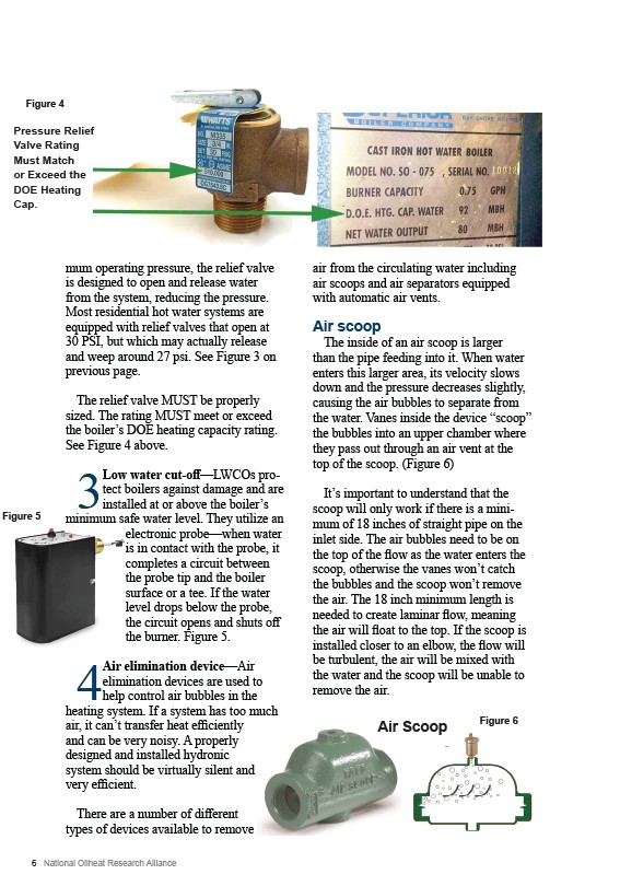
The relief valve MUST be properly
sized. The rating MUST meet or exceed
the boiler’s DOE heating capacity rating.
See Figure 4 above.
3 Low water cut-off—LWCOs protect
boilers against damage and are
installed at or above the boiler’s
minimum safe water level. They utilize an
electronic probe—when water
is in contact with the probe, it
completes a circuit between
the probe tip and the boiler
surface or a tee. If the water
level drops below the probe,
the circuit opens and shuts off
the burner. Figure 5.
4 Air elimination device—Air
elimination devices are used to
help control air bubbles in the
heating system. If a system has too much
air, it can’t transfer heat efficiently
and can be very noisy. A properly
designed and installed hydronic
system should be virtually silent and
very efficient.
There are a number of different
types of devices available to remove
6 National Oilheat Research Alliance
air from the circulating water including
air scoops and air separators equipped
with automatic air vents.
Air scoop
The inside of an air scoop is larger
than the pipe feeding into it. When water
enters this larger area, its velocity slows
down and the pressure decreases slightly,
causing the air bubbles to separate from
the water. Vanes inside the device “scoop”
the bubbles into an upper chamber where
they pass out through an air vent at the
top of the scoop. (Figure 6)
It’s important to understand that the
scoop will only work if there is a minimum
of 18 inches of straight pipe on the
inlet side. The air bubbles need to be on
the top of the flow as the water enters the
scoop, otherwise the vanes won’t catch
the bubbles and the scoop won’t remove
the air. The 18 inch minimum length is
needed to create laminar flow, meaning
the air will float to the top. If the scoop is
installed closer to an elbow, the flow will
be turbulent, the air will be mixed with
the water and the scoop will be unable to
remove the air.
Figure 6
Pressure Relief
Valve Rating
Must Match
or Exceed the
DOE Heating
Cap.
Air Scoop