6. Adjust the barometric draft control to
obtain the appliance manufacturer’s recom-mended
draft at the breech and over the fire.
The draft control gate should be open ap-proximately
half its full swing during normal
operation.
7. If the proper draft cannot be obtained
at the breech or if the gate does not open as
described, adjust the choke plate to reduce or
increase the airflow. Readjust the draft control
to obtain the required draft (adjusting the choke
plate changes the system draft).
8. Once the proper draft is obtained, perform
a smoke test and adjust the burner air intake
(if necessary) to obtain zero smoke. As the air
intake is adjusted, the draft may change. If it
does, repeat steps 4 through 8 to readjust the
draft control and choke plate before continuing.
9. Calculate the combustion efficiency and
verify it is at the manufacturer's recommenda-tion
with zero smoke. Measure the exhaust gas
temperature at the power vent inlet and confirm
it is within the manufacturer's recommenda-tion,
typically between 200°F and 500°F.
10. If the manufacturer’s recommended
efficiency at zero smoke yields a temperature
below 200° F at the inlet to the venter, the fol-lowing
suggestions must be considered:
A. Increase the firing rate if the appliance
manufacturer’s instructions allow it.
B. Insulate the flue pipe to minimize heat
loss.
C. Seal the flue pipe joints to reduce
uncontrolled dilution air.
D. Minimize the vent length from the
appliance to power vent system.
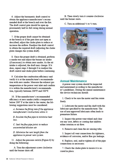
11. Adjust the pressure switch (Figure 8) by
doing the following:
A. Turn the adjustment screw clockwise
until the burner shuts off.
30 National Oilheat Research Alliance
B. Then slowly turn it counter-clockwise
until the burner starts.
C. Turn an additional ¼ to ½ turn.
Annual Maintenance
A power-vent system should be inspected
and maintained according to the manufactur-er’s
guidelines. During the annual maintenance
the service technician should:
1. Check to be sure the motor and fan rotate
freely.
2. Lubricate the motor and fan shaft with the
lubricant specified by the manufacturer. The
use of non-approved lubricants often leads to
premature failure.
3. Inspect the power-vent wheel and clear
out any soot, debris or coating that inhibits
either rotation or air flow.
4. Remove and clean the air sensing tube.
5. Inspect all vent connections for tightness,
evidence of corrosion, and/or flue gas leakage.
6. Replace, seal, and/or tighten all of the pipe
connections as necessary.
7. Check the choke plate to insure it is se-cured
in place.
Figure 8