Power Vent
Power vents are mounted near or on the
outside of the building and pull the combustion
gases from the appliance using negative
pressure. They require controls that interlock
with the appliance control circuit to ensure that
proper draft is established before the oil burner
is activated. A power vent control system
includes a draft-proving switch and either a
thermal or timed post purge cycle.
Figure 3
26 National Oilheat Research Alliance
Power vent systems are available as a
combination unit that can also supply outdoor
combustion air to the burner. These units
combine the benefits of power vent with those
of “air boots” direct connect combustion air
explained in Chapter 1.
How a Power Vent System Works
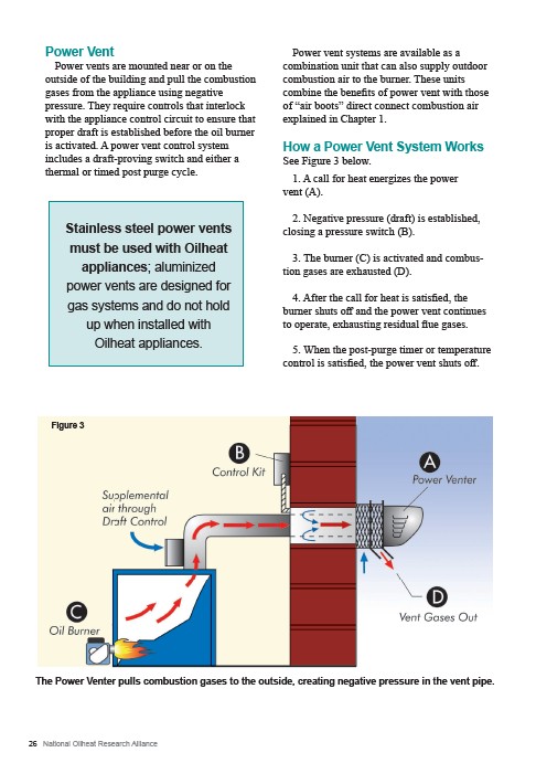
See Figure 3 below.
1. A call for heat energizes the power
vent (A).
2. Negative pressure (draft) is established,
closing a pressure switch (B).
3. The burner (C) is activated and combus-tion
Figure 1
Stainless steel power vents Conduction
must be used with Oilheat
appliances; aluminized
power vents are designed for
gas systems and do not hold
up when installed with
Oilheat appliances.
gases are exhausted (D).
4. After the call for heat is satisfied, the
burner shuts off and the power vent continues
to operate, exhausting residual flue gases.
5. When the post-purge timer or temperature
control is satisfied, the power vent shuts off.
The Power Venter pulls combustion gases to the outside, creating negative pressure in the vent pipe.