Important
National Oilheat Research Alliance 11
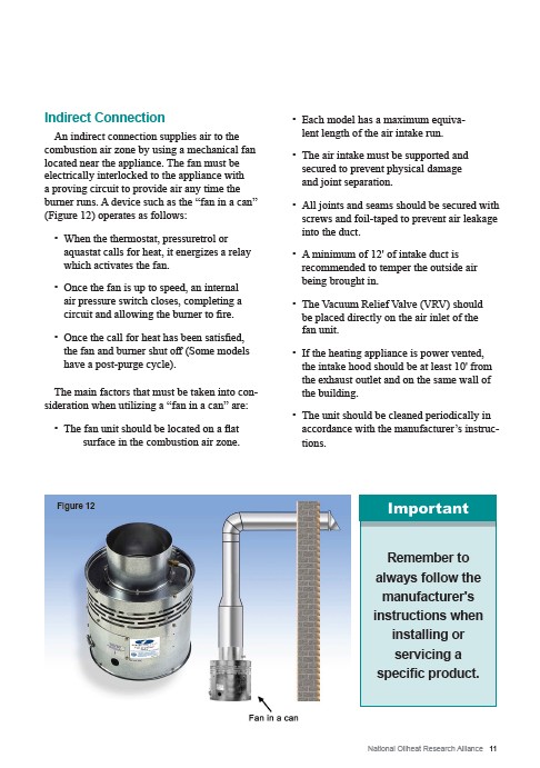
Indirect Connection
An indirect connection supplies air to the
combustion air zone by using a mechanical fan
located near the appliance. The fan must be
electrically interlocked to the appliance with
a proving circuit to provide air any time the
burner runs. A device such as the “fan in a can”
(Figure 12) operates as follows:
• When the thermostat, pressuretrol or
aquastat calls for heat, it energizes a relay
which activates the fan.
• Once the fan is up to speed, an internal
air pressure switch closes, completing a
circuit and allowing the burner to fire.
• Once the call for heat has been satisfied,
the fan and burner shut off (Some models
have a post-purge cycle).
The main factors that must be taken into con-sideration
when utilizing a “fan in a can” are:
• The fan unit should be located on a flat
surface in the combustion air zone.
• Each model has a maximum equiva-
lent length of the air intake run.
• The air intake must be supported and
secured to prevent physical damage
and joint separation.
• All joints and seams should be secured with
screws and foil-taped to prevent air leakage
into the duct.
• A minimum of 12' of intake duct is
recommended to temper the outside air
being brought in.
• The Vacuum Relief Valve (VRV) should
be placed directly on the air inlet of the
fan unit.
• If the heating appliance is power vented,
the intake hood should be at least 10' from
the exhaust outlet and on the same wall of
the building.
• The unit should be cleaned periodically in
accordance with the manufacturer’s instruc-tions.
Figure 12
Remember to
always follow the
manufacturer's
instructions when
installing or
servicing a
specific product.