NOTE:
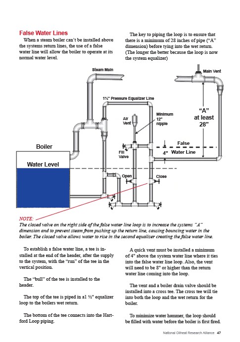
The closed valve on the right side of the false water line loop is to increase the systems “A”
dimension and to prevent steam from pushing up the return line, causing bouncing water in the
boiler. The closed valve allows water to rise in the second equalizer creating the false water line.
National Oilheat Research Alliance 47
Steam Main
1½" Pressure Equalizer Line
Main Vent
“A”
at least
28"
Minimum
12"
nipple
Air
Vent
Fill
Valve
False
4" Water Line
Boiler
Water Level
Open Close
False Water Lines
When a steam boiler can’t be installed above
the systems return lines, the use of a false
water line will allow the boiler to operate at its
normal water level.
To establish a false water line, a tee is installed
at the end of the header, after the supply
to the system, with the “run” of the tee in the
vertical position.
The “bull” of the tee is installed to the
header.
The top of the tee is piped in a1 ½" equalizer
loop to the boilers wet return.
The bottom of the tee connects into the Hartford
Loop piping.
The key to piping the loop is to ensure that
there is a minimum of 28 inches of pipe (“A”
dimension) before tying into the wet return.
(The longer the better because the loop is now
the system equalizer)
A quick vent must be installed a minimum
of 4" above the system water line where it ties
into the false water line loop. Also, the vent
will need to be 8" or higher than the return
water line coming into the loop.
The vent and a boiler drain valve should be
installed into a cross tee. The cross tee will tie
into both the loop and the wet return for the
boiler.
To minimize water hammer, the loop should
be filled with water before the boiler is first fired.